Project 510: FMIC + more (pt 3)
Part 3, here we go. To quickly re-cap, Part 1 was all about relocating the alternator with custom mounts, and Part 2 saw the intercooler and radiator bolted into place, and the intercooler piping tacked together. Now we’re getting down to the finer details.
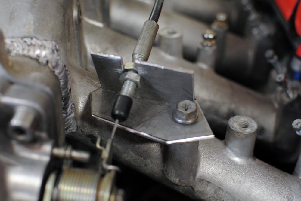
The S12 manifold I bought was quite bare, so I needed an accelerator cable bracket because my DR30 one was not compatible. I decided I’d just make my own.
I broke out the scrap metal pile once again and found some 1mm plate. After a bit of work with the angle grinder and drill I had my basic shape.
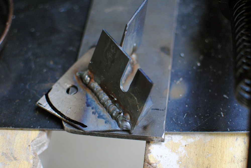
To weld it together I used the ‘thin metal technique’ which is a series of hot tacks joined together. This worked well for me.
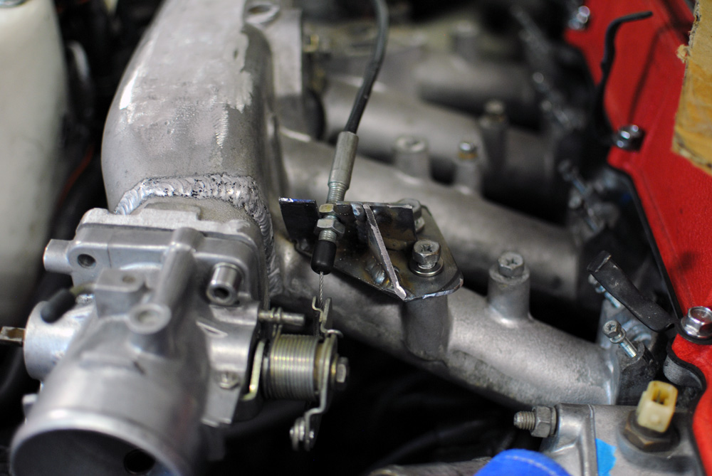
The finished piece (with added gusset)
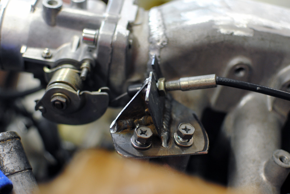
Side angle.
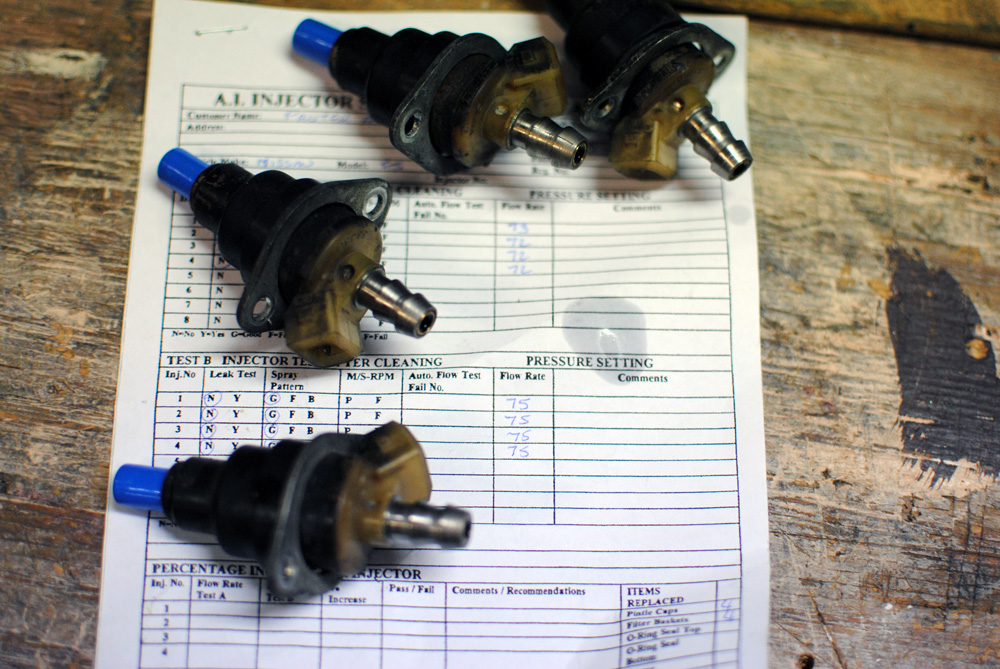
While I had the injectors out I thought it would be a good idea to have them professionally cleaned and flow-tested. It turned out that they were actually quite good, but we still managed to extract a bit out of them and get them all equal.
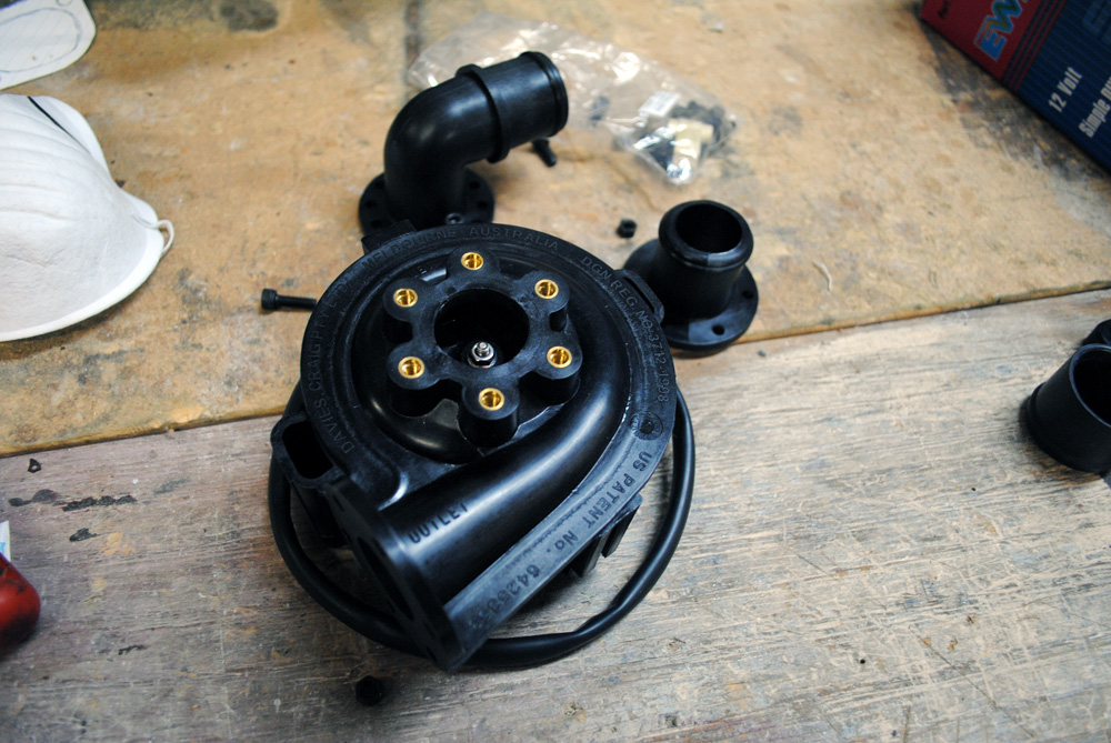
Let’s move away from the intake for a minute and talk about the electric water pump. I chose a Davis Craig EWP80, and as you can see above it comes with a couple of different flanges that you can bolt on to the inlet and outlet.
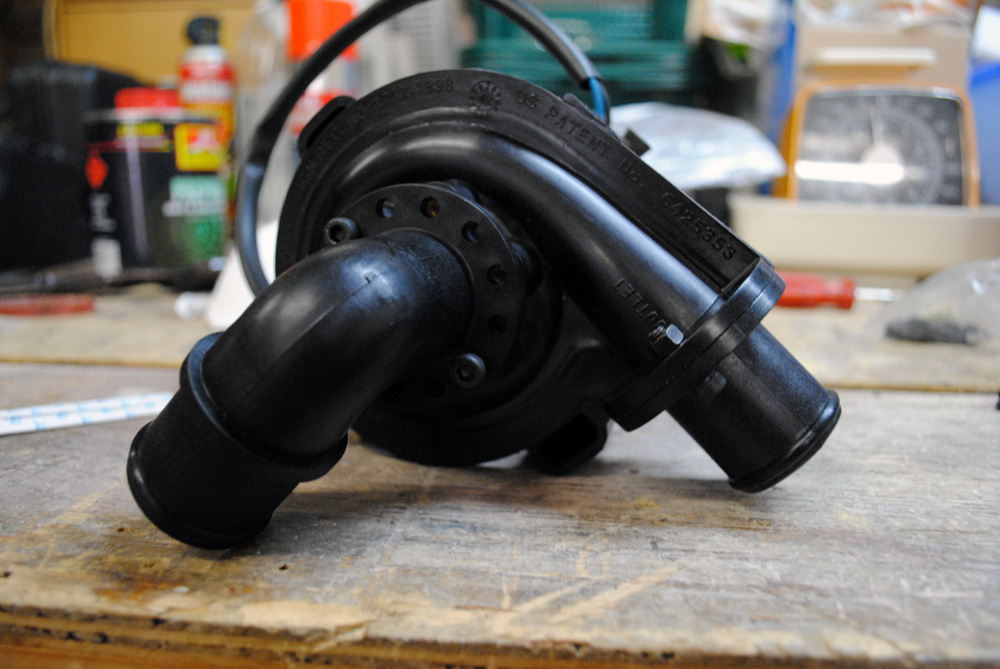
This is the combination I went with, except I needed the outlet (to the right of the picture) to face the other direction. This is simple enough as the housing can be loosened and rotated (albeit carefully), much like a turbo.
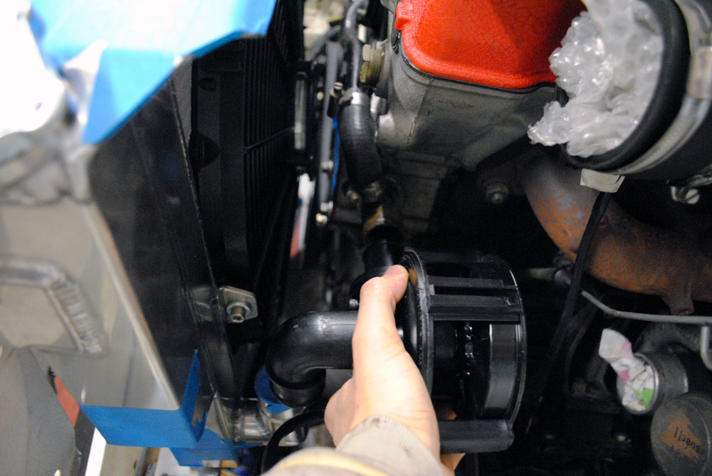
With the housing rotated you can see how lucky I was with the placement. The inlet of the pump points down straight into the vertical facing lower radiator outlet, and the pump outlet points straight into the engine. This means all I needed was two short and straight hoses. Davis Craig recommends that you do not hard-mount these pumps, but simply let the hoses hold them in place. If you solid-mount them you can risk damaging them.
Time for more fabrication…

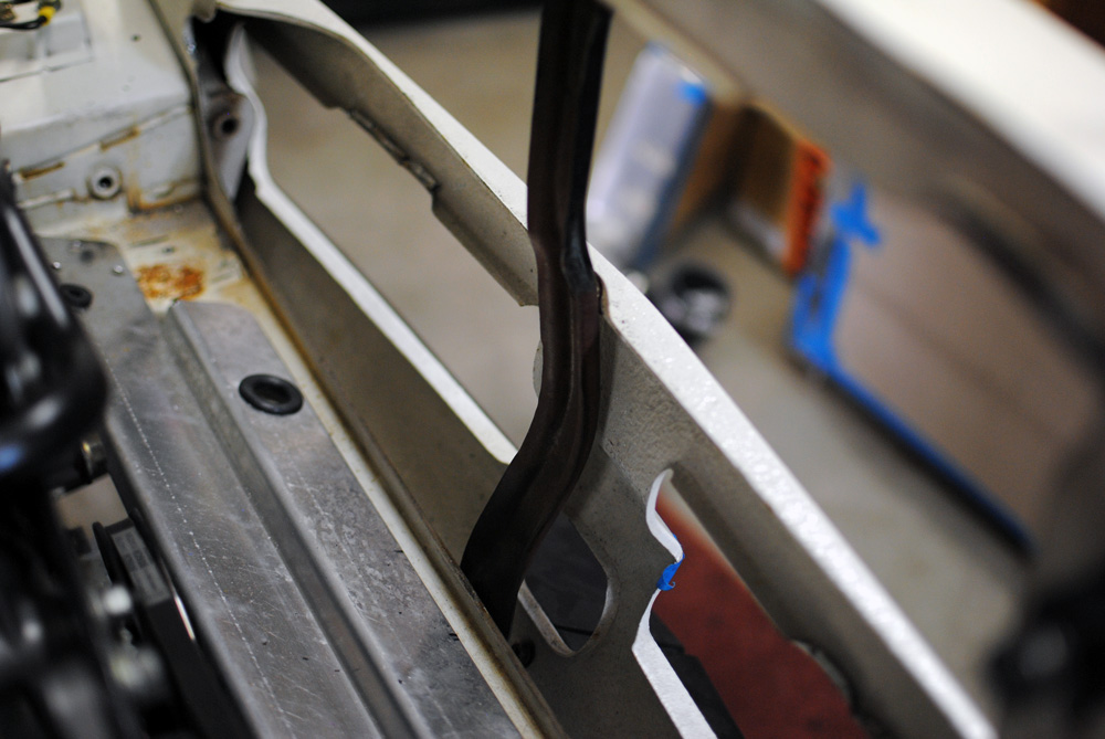
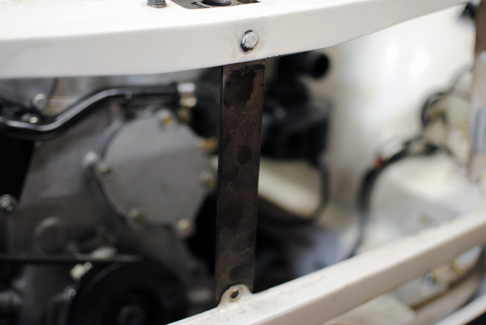
In the above images you’ll see the factory radiator support bracket. This sits behind the grille and ties the front of the car together in 3 places. Unfortunately with my new intercooler now taking up some real estate the factory item would no longer fit, so I had to modify it or make my own. I chose to make my own (duh!).
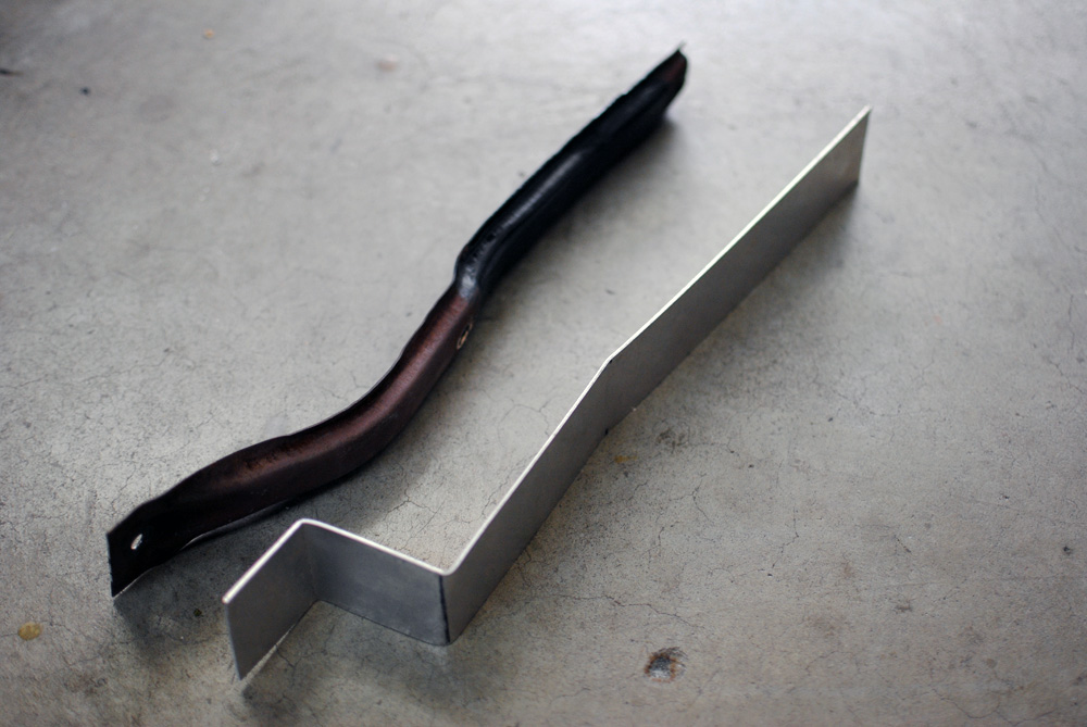
Much like the alternator bracket, I started off with a quick and easy aluminium mock-up. Here it is compared to the factory bracket.
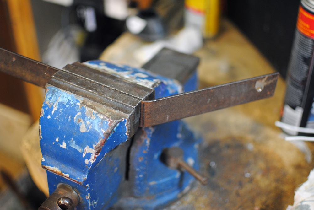
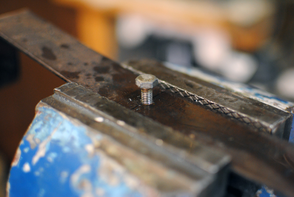
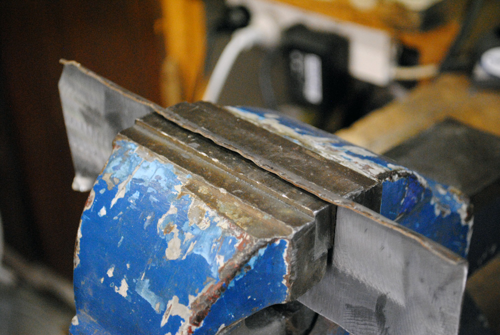
Once I got it to a point where I knew it would work, I made another one out of some thicker steel by marking the fold lines and bending it in the vise. I used a thicker metal compared to the original bracket, since the original was a stamped shape with folds in it to give it strength, whereas mine was just a flat piece of metal.
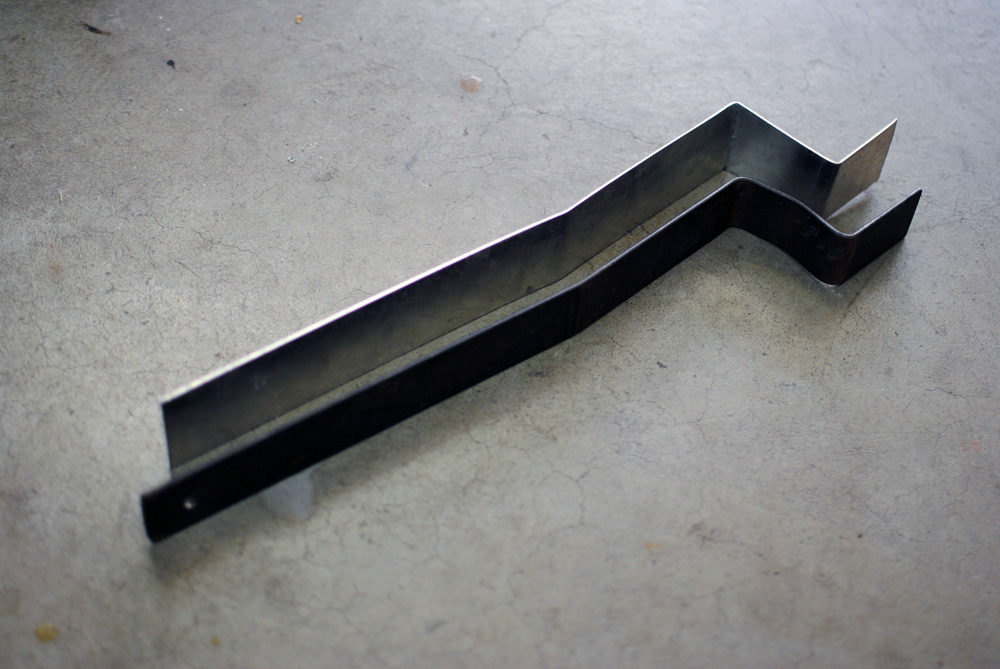
Here is the steel version next to the aluminium mockup.
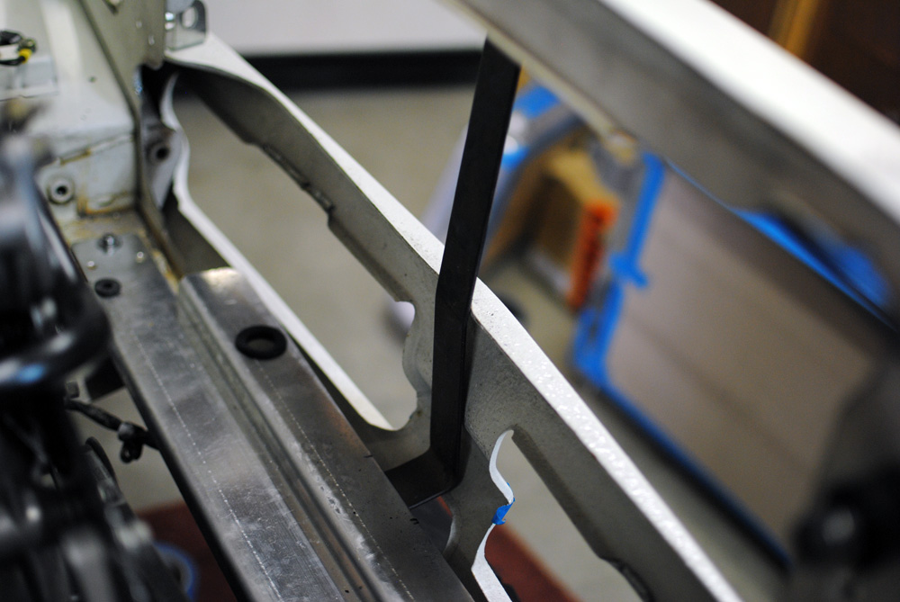
Test fitting on the car to make sure it doesn’t hit the front apron.
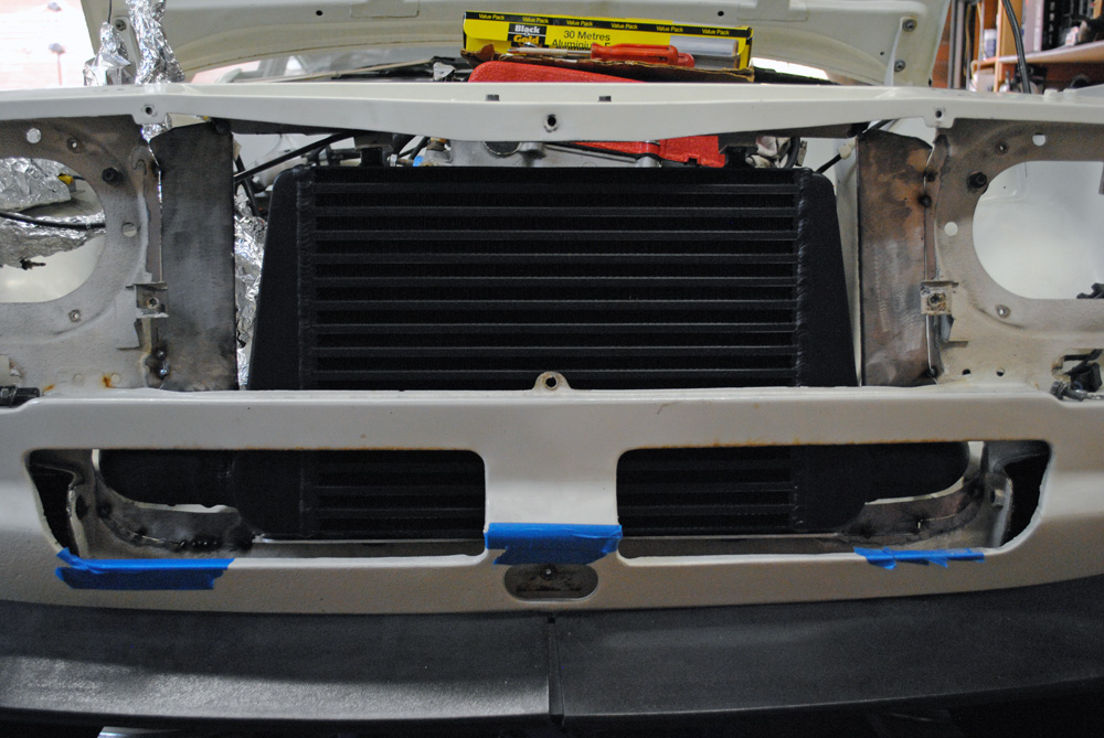
The true test was to put the intercooler into place and make sure it all fit together.
Great success!
At this point I had only drilled and tapped the top hole. Now that I knew the shape worked, I could drill and tap the second hole, and drill the 3rd hole, as the third bolt is screws into a thread in the body of the car. I used the same distance between holes as the factory item so everything would line up the same as before.

All done!
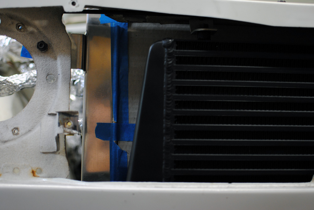
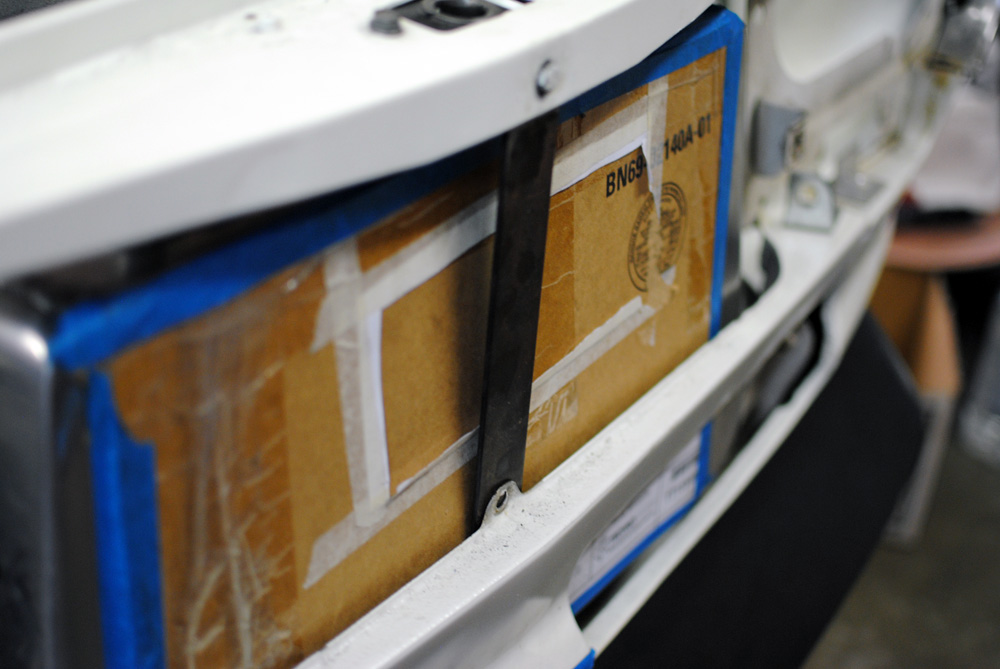
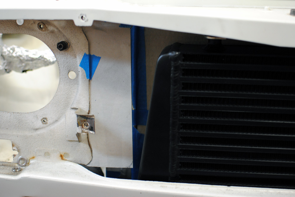
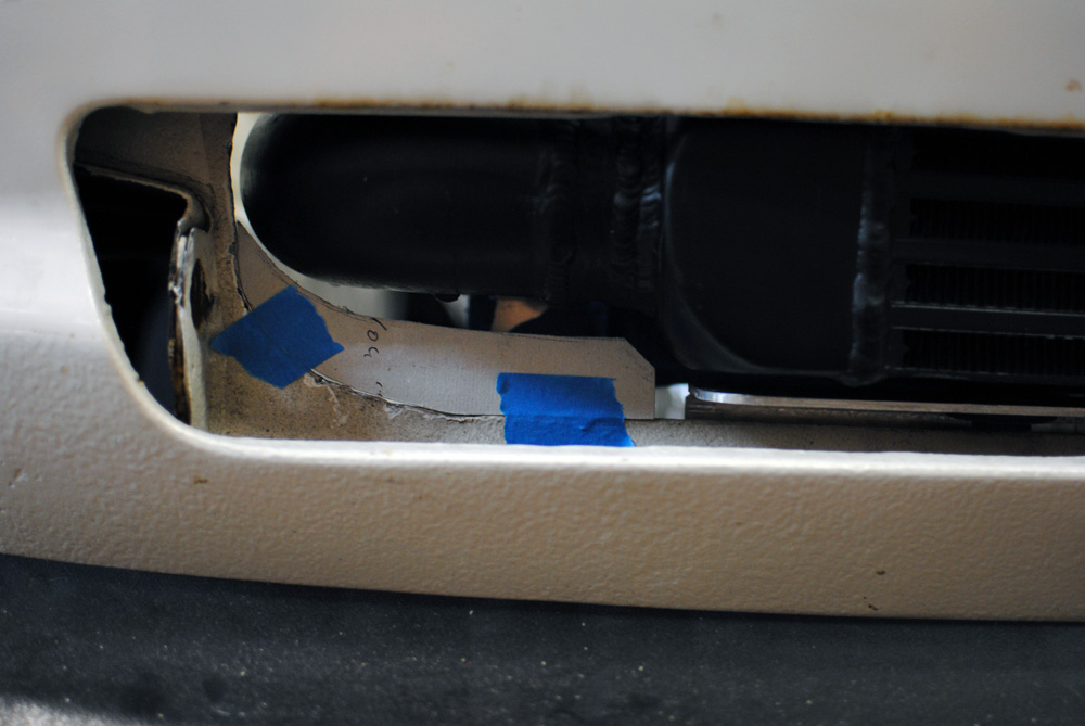
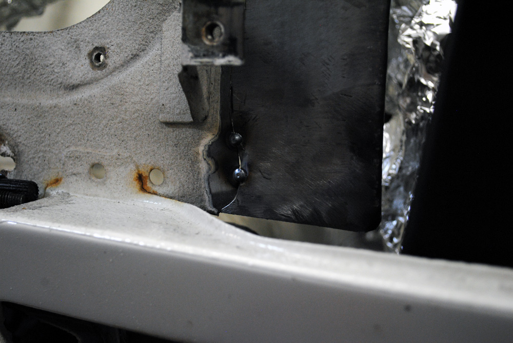
One of the last bits of fabrication that I tackled was to add in some metal to the radiator support panel. As you can see in the above image, there is a big gap between the body and the radiator. Because my previous radiator was so big and wide, the previous owner had cut a lot of metal out of the front of the car.
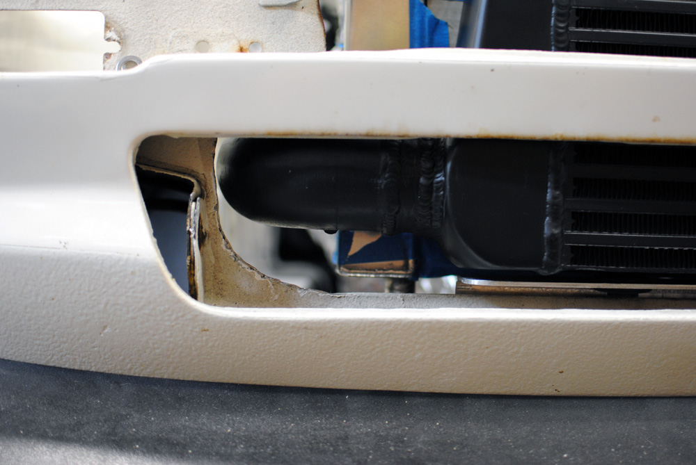
It was a similar story down below near the intercooler. These gaps would allow air to go straight into the engine bay, letting in dirt and debris. Not only that, the air would be better utilised if it was directed at the radiator and intercooler instead of going straight past it.
So it was out with the cardboard and scissors to make some templates that followed the shape of the radiator and intercooler.
I’ve only showed you the driver’s side so far but it was the same on the other side.
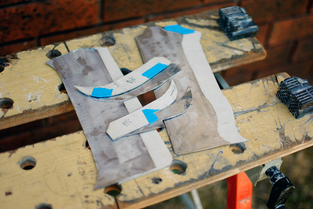
Next the templates were transferred onto 1mm metal. This metal had some sort of zinc in it, even after I grinded off the top layer, so it wasn’t very good to weld. Before you school me I have read up on zinc flu and all that stuff, but I was only doing short tack welds and I had a dust mask on and a fan behind me to blow away any fumes.
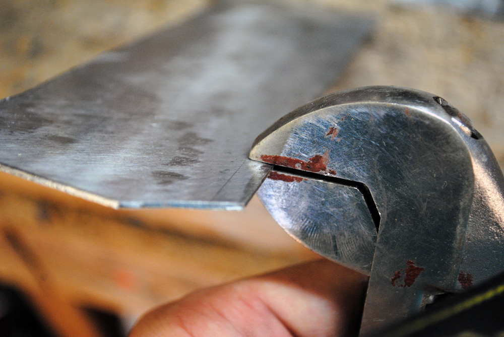
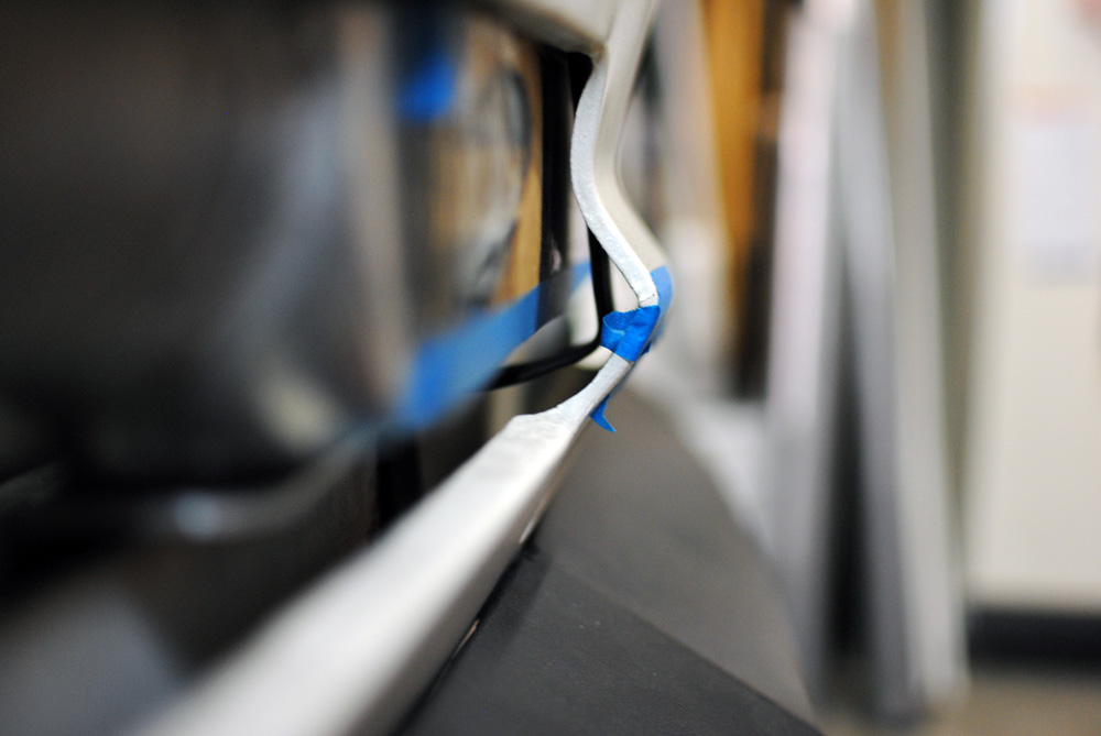
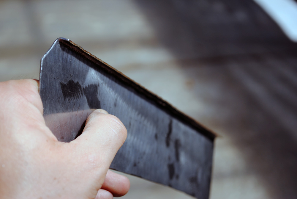
I wanted to add some rigidity and a nice clean edge to the two vertical pieces. To do this I scribed a line and then took a shifter spanner adjusted to the same thickness as the metal and slowly bent the edge into shape.
Which gives you something like this.
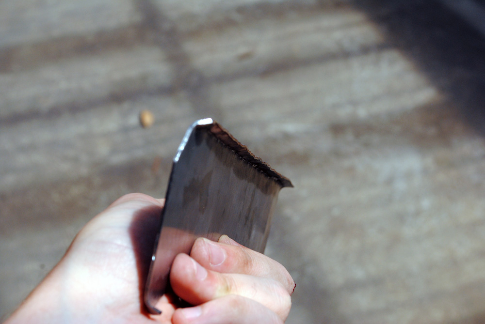
Next I put it in the vise and started hammering the lumps and bumps into shape.
And this is how it turned out. Noice!
Here are all 4 pieces tacked into place.
Close-up.
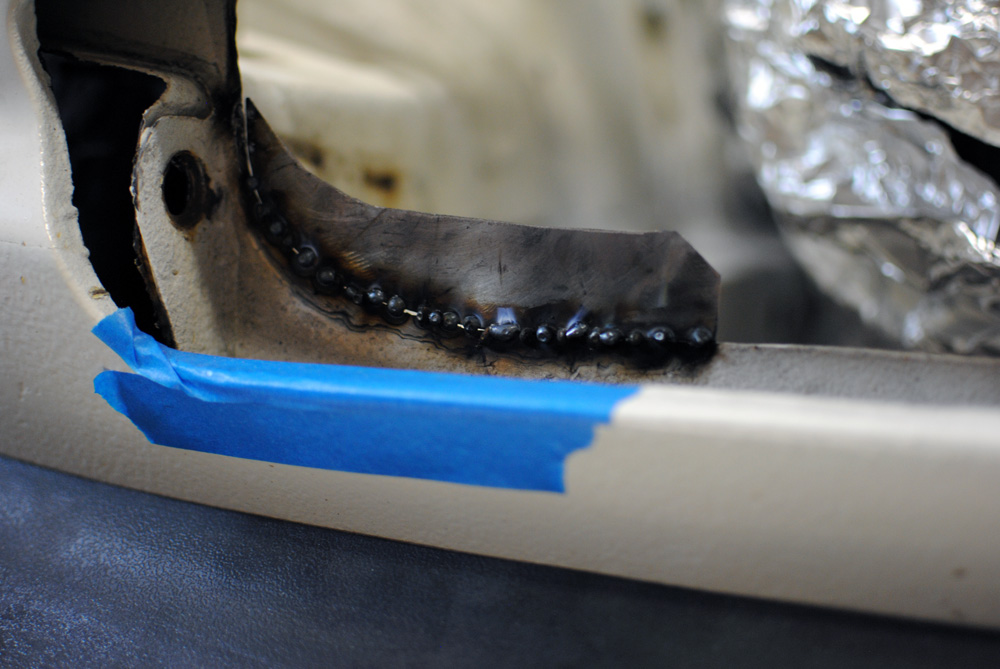
I slowly joined up the tack welds until there was no gaps, ground down the welds, and then filled up any more gaps. I would do a few tacks on one piece, then move onto the next, and make my way around the 4 different pieces so as not to heat up the metal too much and reduce the chance of distortion.
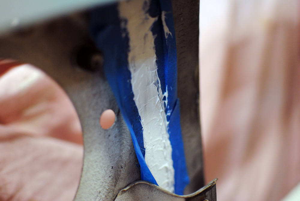
Once the welding was complete I sealed it all up with Sikaflex on both the front and back. If I could do this again I would have overlapped the new pieces with the existing metal instead of butt-welding, this would have allowed me to make simpler shaped pieces and would have made the welding much easier.
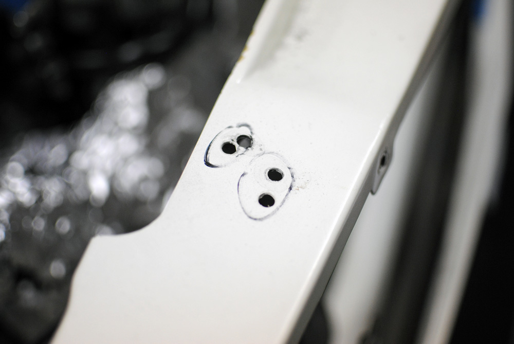
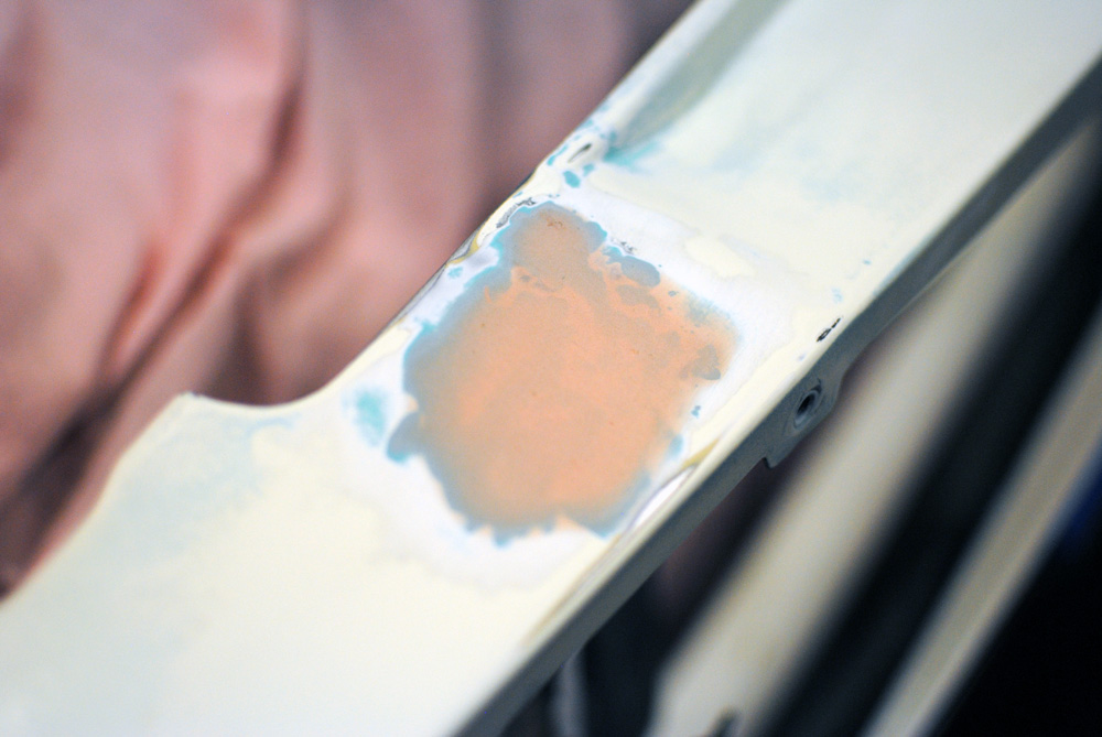
Before the welder was wheeled away, I needed to fill up some holes on the top of the radiator support panel. This is where the old radiator mounts were bolted in.
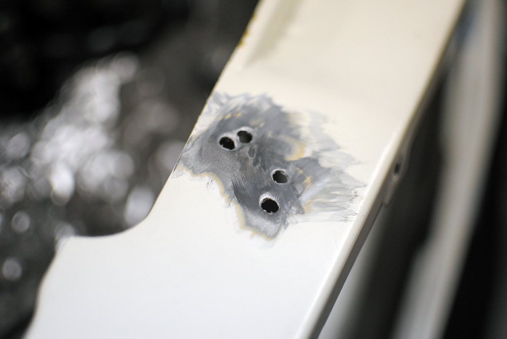
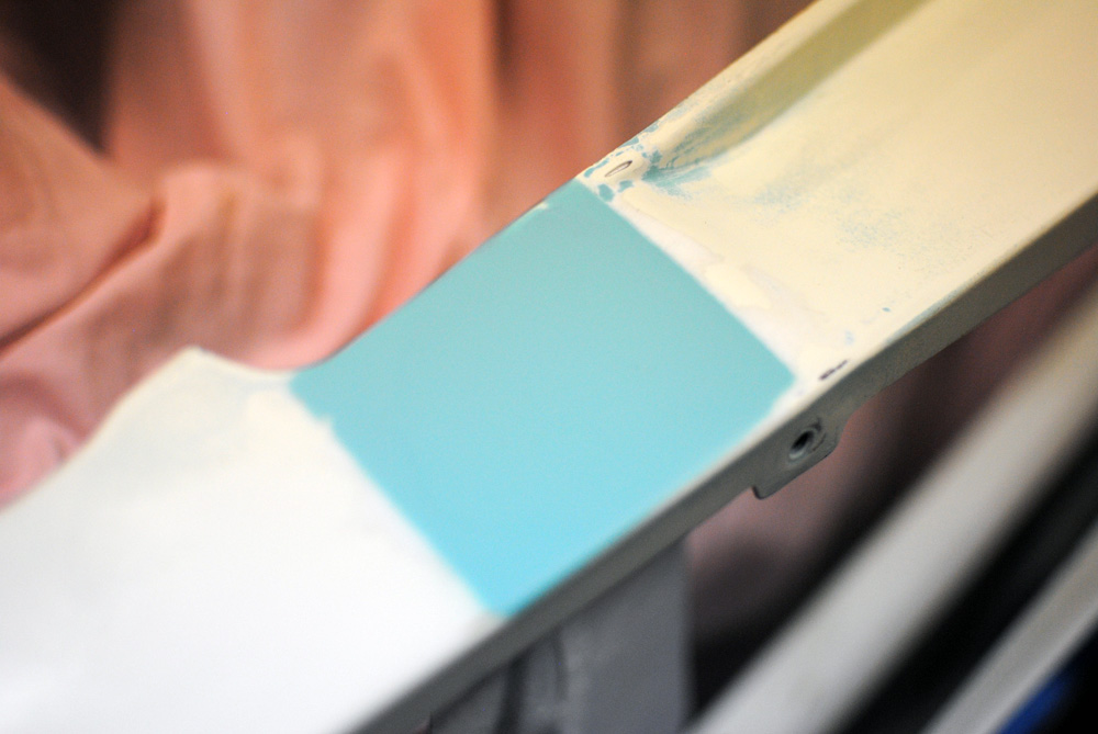
First the paint was ground back.
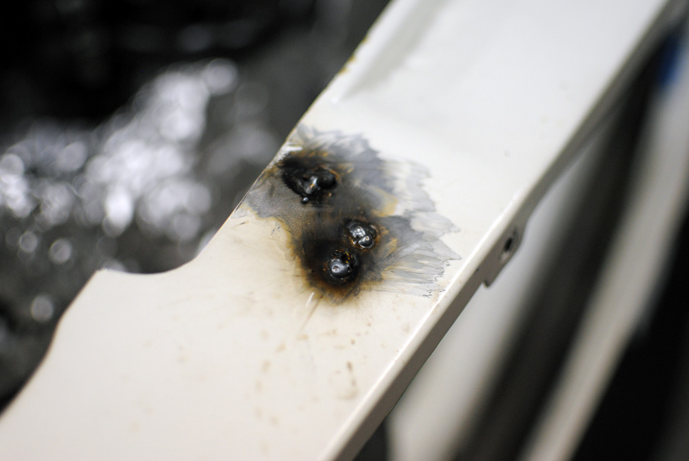
Then the holes were welded up. I used some 10c coins underneath to help.
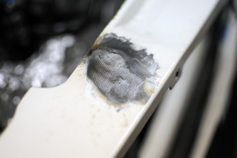
Ground back.
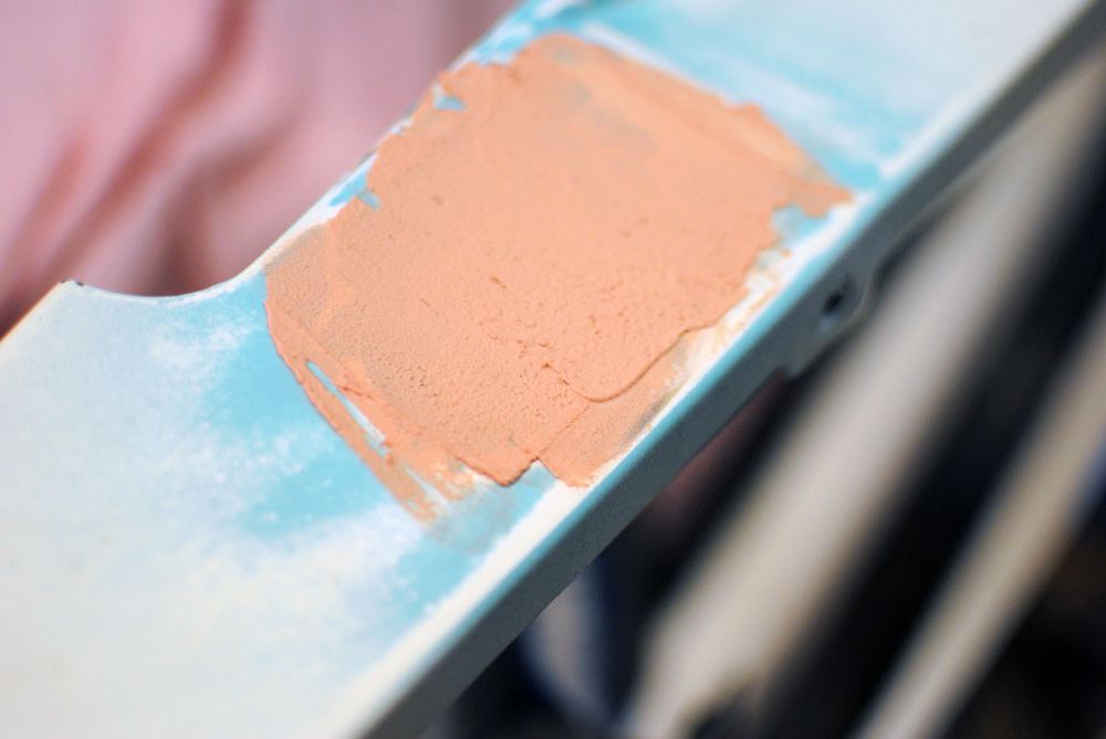
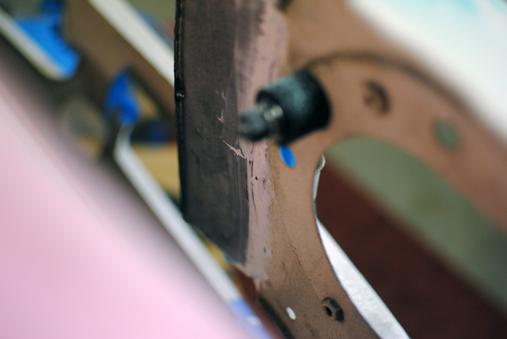
A little bit of filler was used to even everything out.
Sanded back.
And finally a coat of high-build primer.
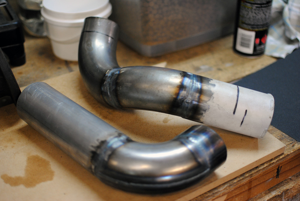
I’ll finish this post off with a picture of my final intercooler piping that I had tig welded by Dom at Protek after I had tacked them together.
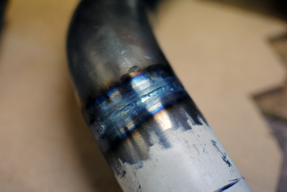
The tig welds are much neater than I could ever dream to achieve on my mig, and I know they’ll be leak-free.
The next update will be getting everything looking pretty and getting stuck into final assembly. Sorry to drag this out but it was just too much to put into a single post, I hope you’re enjoying it.
Original: Build Threads